Dedicated to information on Joe Trumbly, the Bates Boatbuilding Program, and Tacoma boatbuilding
Shaft-boring jig
This section illustrates the shaft-boring jig used to bore long propeller- and rudder-shaft holes. To my knowledge, this tool was not commercially produced, and shops had to have it specially built in a welding or machine shop. This tool takes some of the guesswork out of drilling shaft holes. A relatively narrow guide hole is drilled first by sight and estimation. The jig’s cutting rod is then inserted through the guide hole and held in place in the correct position by a bearing clamped at each end of the guide hole. An adjustable bit on the cutting rod allows holes of various diameters to be bored. The beauty of the shaft-boring jig is that it allows an accurate shaft hole to be drilled even if the guide hole emerges somewhat off center. The Bates shop had a shaft-boring jig, which Trumbly would let students borrow for off-campus work, but he would lend it only to current students, over whom he had some leverage to ensure the jig was returned. Some of the photos from other sections are repeated here because they also deal with the shaft-boring jig.
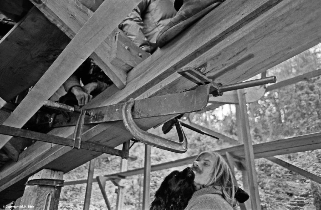
Windance; shaft-boring jig clampled in place, seen from underside of keel.
Windance: shaft-boring jig clamped in place, seen from underside of keel, showing the adjustable outer bearing. Note that the cutting shaft is not centered in the guide hole.
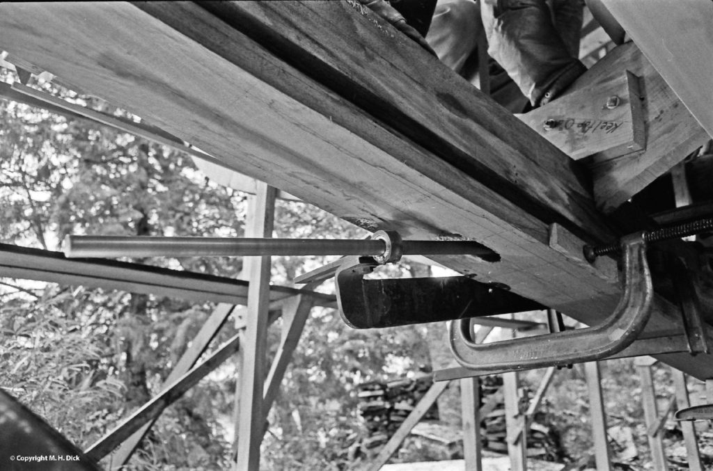
Windance: another view of shaft-boring jig, from the side.
Windance: outside bearing and cutting rod, shaft-boring jig.
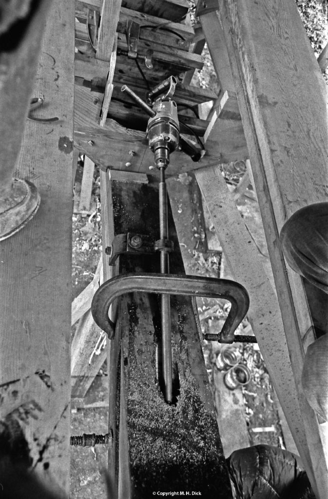
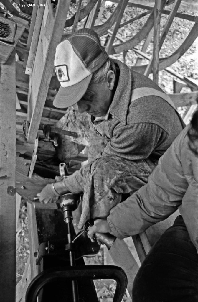
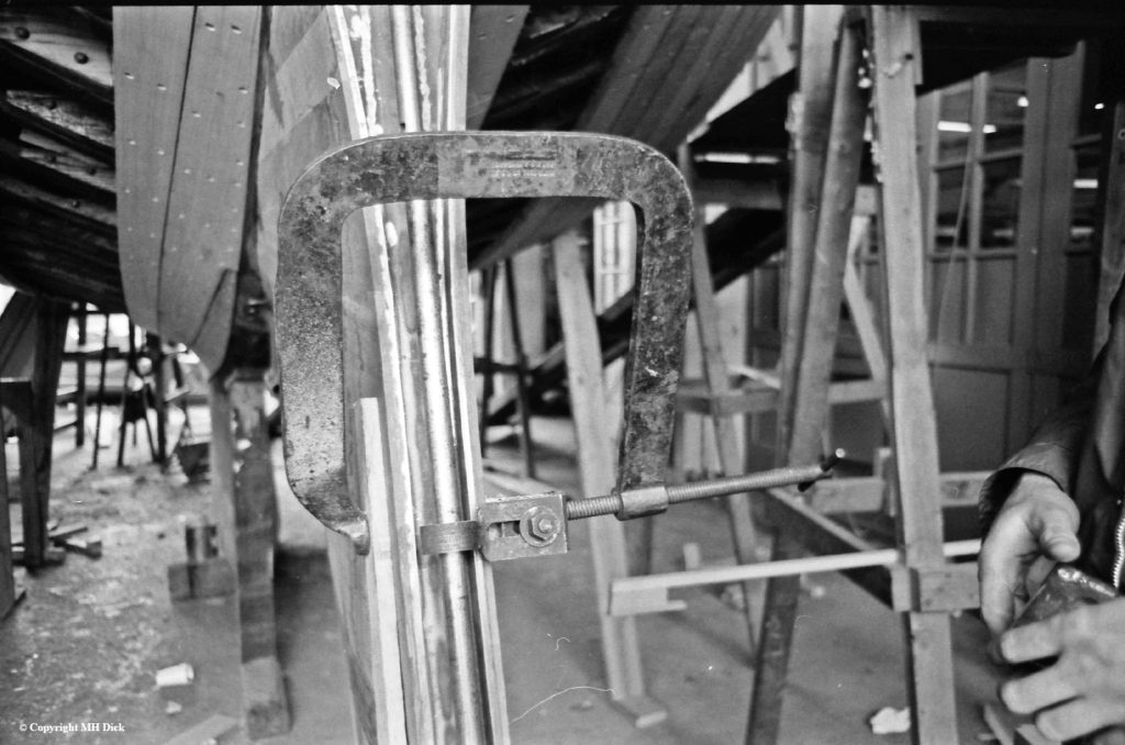
Windance: heavy-duty drill motor used to turn cutting rod. The inside bearing is visible just above the C-clamp.
Windance: Trumbly using calipers to set cutter to bore a two-inch shaft hole.
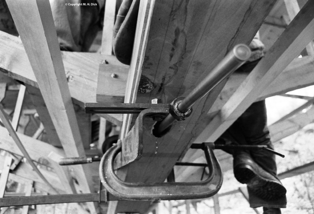
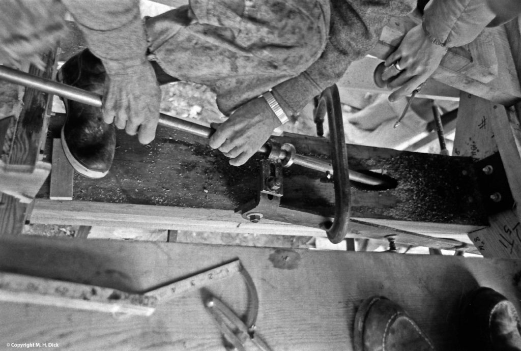
Windance: shaft-boring jig in place, seen from top side of keel. Note the cutting bit projecting from the cutting rod, just to the left of the C-clamp, adjustable with a set screw.
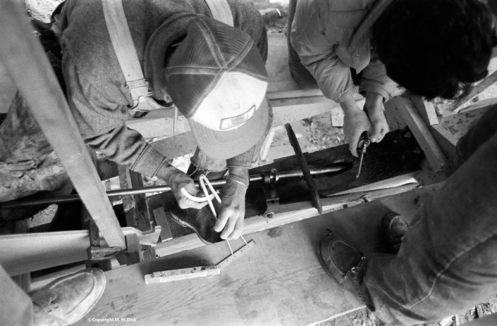
Windance: Trumbly boring the shaft hole; note that a person is oiling the bearing during cutting.
Trumbly 38: Setting up to bore the rudder-shaft hole. George Chambers (below) has clamped the outside bearing in place on the rudder fin; Patrick Chapman (above) is inserting the cutting rod into the guide hole.
Trumbly 38: George Chambers checking the alignment of the cutting rod.
Trumbly 38: the clamp holding the outside bearing, with the cutting rod in place.